Well, I need some info on this subject, so it seems like a good time to start this thread.
I am planning to use the later style factory disc brakes on my 14-bolt. I have rounded up most of the parts for the disc brakes, but I'm not convinced everything is right. Specifically, the backing plate assembly seems incorrect.
Everything I can find says that the same part number plate is used for both the left and right brakes. Instead, I would expect that these assemblies would be mirror images of each other.
This is a photo of the backing plate assembly. The part number is 88965717.
Can somebody confirm that this assembly is used at both ends of the axle (or not)? If somebody happened to have some photos of each end of the axle (assembled), that would be great! The parking brake cable routing to the backing plate assembly also seems suspect too.
Thanks,
Chris
GM 14-bolt rear axle build
-
mineral co
Topic author - Posts: 229
- Joined: Tue Jul 09, 2013 1:20 pm
- Location: Mineral County, Colorado
GM 14-bolt rear axle build
You do not have the required permissions to view the files attached to this post.
'84 GW, returning to service.
360, 727, Selec-Trac 229, TFI, Hydro-Boost, 4" all-spring BDS lift (what a PITA!), BFG/AT 31x10.5x15, 5125 Bilstiens
360, 727, Selec-Trac 229, TFI, Hydro-Boost, 4" all-spring BDS lift (what a PITA!), BFG/AT 31x10.5x15, 5125 Bilstiens
-
 Stuka
Stuka
- Site Admin
- Posts: 11812
- Joined: Thu May 12, 2011 5:53 pm
- Location: CA
- Contact:
Re: GM 14-bolt rear axle build
Are the bolts that hold it to the axle square, or are they trapezoidal? If they are square, you can rotate the backing plate to be in the same place on both sides. But if not, and it only fits on one way, then they would have to be different.
2017 JKU Rubicon
Pevious Jeeps: 1981 J10, 1975 Cherokee, 2008 JK, 2005 KJ, 1989 XJ
Pevious Jeeps: 1981 J10, 1975 Cherokee, 2008 JK, 2005 KJ, 1989 XJ
-
mineral co
Topic author - Posts: 229
- Joined: Tue Jul 09, 2013 1:20 pm
- Location: Mineral County, Colorado
Re: GM 14-bolt rear axle build
As can be seen in the above photo, the backing plate assembly bolts are trapezoidal.
I've spent several more hours reviewing a bunch of not very good photos on the 'net, and they do imply that the same assembly is used on both ends of the axle. This would mean that the flanges on the axle tubes are at different rotations relative to each other and that the parking brake cables enter the assemblies from the rear instead of a much more logical front approach.
Relative to the standard 14-bolt rear axle, I'm quite surprised at how little concrete information there is on the 'net about the later AAM axles. There is tons of speculation and piles of contradictory statements, but very little in the way of accurate drawings or parts lists or formal literature.
Even one clear photo of each end of a factory stock disc brake AAM axle would clear this mystery up!
Thanks,
Chris
'84 GW, returning to service.
360, 727, Selec-Trac 229, TFI, Hydro-Boost, 4" all-spring BDS lift (what a PITA!), BFG/AT 31x10.5x15, 5125 Bilstiens
360, 727, Selec-Trac 229, TFI, Hydro-Boost, 4" all-spring BDS lift (what a PITA!), BFG/AT 31x10.5x15, 5125 Bilstiens
-
Stuka
- Site Admin
- Posts: 11812
- Joined: Thu May 12, 2011 5:53 pm
- Location: CA
- Contact:
Re: GM 14-bolt rear axle build
And you are right 
This is a 2009 2500. Take a look at the driver side.
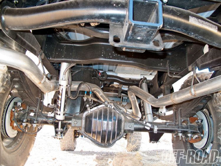
This is a 2009 2500. Take a look at the driver side.
2017 JKU Rubicon
Pevious Jeeps: 1981 J10, 1975 Cherokee, 2008 JK, 2005 KJ, 1989 XJ
Pevious Jeeps: 1981 J10, 1975 Cherokee, 2008 JK, 2005 KJ, 1989 XJ
-
mineral co
Topic author - Posts: 229
- Joined: Tue Jul 09, 2013 1:20 pm
- Location: Mineral County, Colorado
Re: GM 14-bolt rear axle build
Well, I guess I'll just deal with it! (Thanks for the photo.)
I am thinking about rotating the assemblies 180*. This would put the calipers behind the rotor, but would also allow the parking brake cables to enter from the front side like the stock FSJ stuff does.
I've designed some weld-on brackets for the trapezoidal bolt pattern on the backing plate assembly. (Anybody have these dimensions? Would be good to have any sort of related information to double check my work. )
I'm still waiting for the 14-bolt to be removed from the truck it's in. What's an '83 GM Dana 60 worth? I think I can have it if I go to the trouble to pull it out.
I am thinking about rotating the assemblies 180*. This would put the calipers behind the rotor, but would also allow the parking brake cables to enter from the front side like the stock FSJ stuff does.
I've designed some weld-on brackets for the trapezoidal bolt pattern on the backing plate assembly. (Anybody have these dimensions? Would be good to have any sort of related information to double check my work.
I'm still waiting for the 14-bolt to be removed from the truck it's in. What's an '83 GM Dana 60 worth? I think I can have it if I go to the trouble to pull it out.
'84 GW, returning to service.
360, 727, Selec-Trac 229, TFI, Hydro-Boost, 4" all-spring BDS lift (what a PITA!), BFG/AT 31x10.5x15, 5125 Bilstiens
360, 727, Selec-Trac 229, TFI, Hydro-Boost, 4" all-spring BDS lift (what a PITA!), BFG/AT 31x10.5x15, 5125 Bilstiens
-
Stuka
- Site Admin
- Posts: 11812
- Joined: Thu May 12, 2011 5:53 pm
- Location: CA
- Contact:
Re: GM 14-bolt rear axle build
Depends on condition. But I have seen them go for 600-900. They are not worth as much as HP fords, but still desirable.
2017 JKU Rubicon
Pevious Jeeps: 1981 J10, 1975 Cherokee, 2008 JK, 2005 KJ, 1989 XJ
Pevious Jeeps: 1981 J10, 1975 Cherokee, 2008 JK, 2005 KJ, 1989 XJ
-
 Tad
Tad
- Vendor
- Posts: 2267
- Joined: Fri May 13, 2011 4:08 am
- Location: Southern AZ
- Contact:
Re: GM 14-bolt rear axle build
Mine's from an '80 dually, but that's about right.Stuka wrote:Depends on condition. But I have seen them go for 600-900. They are not worth as much as HP fords, but still desirable.
Took me a year to find one that was complete and not bent for under $1K.
A collection of 1966 to 1986 parts.
Self Inflicted Flesh Wound
Caddy425/TH400/Atlas 4spd/14B/D60/locked front and rear/Hydroassist/39.5 Irocks
(Join date = Friday the 13th)
My Stuff:
http://www.ttsfabworks.com/
Tech Stuff:
IFSJA WMS Project
Self Inflicted Flesh Wound
Caddy425/TH400/Atlas 4spd/14B/D60/locked front and rear/Hydroassist/39.5 Irocks
(Join date = Friday the 13th)
My Stuff:
http://www.ttsfabworks.com/
Tech Stuff:
IFSJA WMS Project
-
mineral co
Topic author - Posts: 229
- Joined: Tue Jul 09, 2013 1:20 pm
- Location: Mineral County, Colorado
Re: GM 14-bolt rear axle build
Well, I got the axle, so I've done some measuring and drawing to see what can really be done with the AAM disc brakes and narrowing of the axle.
The caliper sticks out fairly far! The caliper has to be oriented pretty much straight up and down, regardless of whether it's in front of the axle or behind it, otherwise it will hit the U-bolts or spring clamp plate. Oriented vertically, it will clear those obstacles but then the leaf springs are the next obstacle.
In the attached drawing, I have shown the location of the hub flange for both the SRW hub and the dually hub. When using the dually hub the disc would be installed in front of the flange and when using the SRW hub the disc would be installed behind the flange. The error on locating the disc when switching to the SRW hub is 0.225", and a plate of that thickness could be installed between the SRW flange and the disc to keep the disc in the same position relative to the caliper. There are possible wheel stud concerns when doing this and these have not been considered yet.
In order to make room for the parking brake shoes when using the dually hub, the rear of the flange would have to be machined back a fair amount but would still leave the flange thickness at 0.850". That new surface is represented by the dashed verticle line on the flange.
Assuming that the caliper could move backwards by as much as 1/2" as the pads wear (the thickness of the outer brake pad), that leaves only about 1-1/2" that the axle could be shortened on each side (a total of 3"). As it is drawn, the WMS dimension is 63-1/2", so the smallest WMS dimension I can get with this scheme is 60-1/2".
I can push the caliper further out on the axle but, because of the parking brake shoes, I would have to reduce the Dually hub flange thickness by the same amount, and the 0.850" thickness is the thinnest I am currently comfortable with (stock dually flange thickness is 1.525").
So I'm a bit disappointed. I really hoped I could get down to the stock Waggy WMS dimension of 57-1/2" with the dually hub but I just don't see how at this point, short of moving the stock springs inward (which I really don't want to do!)
The drawing is a "rear profile view" but note that the caliper is drawn as though it was over the top of the axle. In practice it will be directly behind the axle, but this would have confused the drawing by making it look like the caliper would overlap the U-bolts and spring plate once the axle had been shortened. The spring assembly has been positioned to reflect the 43-1/2" spring spacing of the Waggy. If anybody's got any ideas for how to improve the amount the axle could be narrowed, I'm all ears! There's probaly a non-floating caliper that could be used, but that would require an additional bracket (not necessarily the end of the world). A wheel with a backspacing different (greater) from the front could be done.
Other possibilities may exist that I haven't considered. Any thoughts?
Thanks,
Chris
You do not have the required permissions to view the files attached to this post.
'84 GW, returning to service.
360, 727, Selec-Trac 229, TFI, Hydro-Boost, 4" all-spring BDS lift (what a PITA!), BFG/AT 31x10.5x15, 5125 Bilstiens
360, 727, Selec-Trac 229, TFI, Hydro-Boost, 4" all-spring BDS lift (what a PITA!), BFG/AT 31x10.5x15, 5125 Bilstiens
-
mineral co
Topic author - Posts: 229
- Joined: Tue Jul 09, 2013 1:20 pm
- Location: Mineral County, Colorado
Re: GM 14-bolt rear axle build
It helps to have the physical parts in hand.
With the brake parts on the axle I see that rotating the caliper downward by 20 degrees will allow the caliper to sit below the leaf springs. In this position, from an interference perspective, it doesn't matter that the caliper body will move even further inboard as the pads wear.
This means that I don't need to allow for a half-inch of caliper movement because of pad wear, plus the initial position of the caliper can be a half-inch further inboard. This gets me another inch on each side, and makes the WMS dimension 58-1/2".
Out of desperation I was trying to find fractions of an inch where ever I could, and this included checking the actual WMS dimension on the Waggy. I was operating under the impression that the stock WMS dimension on Waggys was 57-1/2" as I was told this by a member here that I respect that this was the case. I'm not criticizing as there could always be variations for any number of reasons, and I did note on Dutchman Axle's website that they show several different axle lengths for Waggys, and the '84 and '85 years' are unique. My truck is an '84 and the measured rear WMS dimension is 58-1/2". Tah-Dah! The goal has been achieved!
For reference, I measured from the "face-of-drum to face-of-drum". These are the surfaces that the wheels actually mate to and, by my way of thinking, is the definition of WMS.
Rotating the calipers down by 20* does put them at greater risk from road obstacles. They will stick out beyond the tire's inside edge by about 1-1/2" with the WMS dimension of 58-1/2" (and the inside of the tire will be about 1" from the leaf spring, the same as it is now in stock form). When switching to the SRW hubs, they will stick out about 3-1/2" assuming the same 10.5" tire width. Even with a 12.5" wide tire they will stick out about 2-1/2".
More importantly, at a 20* downward rotation, the lowest point on the caliper assembly will be about 4-1/2" below the axle tube, about an inch lower than with the calipers in their stock GM verticle orientation. For this reason I'm thinking that I should put the calipers in front of the axle tube rather than behind it so that a "hit" would push the caliper into the rotor rather than possibly tear it off the vehicle and sever the brake line. Perhaps even a shield of some type could be incorporated to offer additional protection to the caliper.
I'm open to all thoughts! I did confirm that the pinion is dead center of the axle assembly on my Waggy's AMC-20 axle (as best as I can determine with a tape measure), but the 14-bolt's pinion is actually offset from center by about 3/4". That can be corrected easily during the narrowing exercise.
You do not have the required permissions to view the files attached to this post.
'84 GW, returning to service.
360, 727, Selec-Trac 229, TFI, Hydro-Boost, 4" all-spring BDS lift (what a PITA!), BFG/AT 31x10.5x15, 5125 Bilstiens
360, 727, Selec-Trac 229, TFI, Hydro-Boost, 4" all-spring BDS lift (what a PITA!), BFG/AT 31x10.5x15, 5125 Bilstiens
-
mineral co
Topic author - Posts: 229
- Joined: Tue Jul 09, 2013 1:20 pm
- Location: Mineral County, Colorado
Re: GM 14-bolt rear axle build
I had designed some test adaptor plates so I could bolt the caliper and backing plate to the axle in order to confirm all the dimensions. I'm pretty good with a caliper, but there is always the possibility of error when reverse engineering something. I got the plates today, so I got all excited to do the first test fit. It went well!
This is the 2D drawing of the test adaptor plate(s). I put a circle of holes in it so that the plate could be oriented at any increment of 30 degrees around the axle's original drum brake backing plate flange. I was most concerned about the correctness of the disc brake backing plate's bolts which are arranged in a trapezoidal pattern, and I had intentionally made those holes just barely big enough for the 16 mm bolts to fit in. This would make it easier to recognize an error in bolt spacing, but the bolts slid right in. One hurdle crossed! I neglected to get a photo of the finished plates before installing them, but you can see them installed in the following photos.
The disc brake backing plate bolted to the axle: I bought a couple rotors for determining sizes. They have only about 5mm difference in height or diameter. I think the one I selected is actually from a 14b SF 3/4 ton AAM axle. The rotor is attached to the rear side of a SRW hub for the initial tests.
You do not have the required permissions to view the files attached to this post.
'84 GW, returning to service.
360, 727, Selec-Trac 229, TFI, Hydro-Boost, 4" all-spring BDS lift (what a PITA!), BFG/AT 31x10.5x15, 5125 Bilstiens
360, 727, Selec-Trac 229, TFI, Hydro-Boost, 4" all-spring BDS lift (what a PITA!), BFG/AT 31x10.5x15, 5125 Bilstiens
-
mineral co
Topic author - Posts: 229
- Joined: Tue Jul 09, 2013 1:20 pm
- Location: Mineral County, Colorado
Re: GM 14-bolt rear axle build
Then it was time to install the caliper! This I was anxious about as the rotor needs to sit right in the center of the caliper bracket and there weren't any good flat surfaces to take measurements from. As it turns out, it is nearly perfect.
At that point the only thing left to do is stick a wheel and tire on there! As anticipated, when using the SRW hub, the caliper sticks out about 3-1/2" in the inside.
You do not have the required permissions to view the files attached to this post.
'84 GW, returning to service.
360, 727, Selec-Trac 229, TFI, Hydro-Boost, 4" all-spring BDS lift (what a PITA!), BFG/AT 31x10.5x15, 5125 Bilstiens
360, 727, Selec-Trac 229, TFI, Hydro-Boost, 4" all-spring BDS lift (what a PITA!), BFG/AT 31x10.5x15, 5125 Bilstiens
-
mineral co
Topic author - Posts: 229
- Joined: Tue Jul 09, 2013 1:20 pm
- Location: Mineral County, Colorado
Re: GM 14-bolt rear axle build
This is the anticipated approximate position of the caliper once permanently installed on the left wheel. Note the brake hose is actually for the right wheel and will route over the top of the caliper instead under the bottom as shown in this picture.
And this is the anticipated approximate position of the caliper once permanently mounted on the right wheel. The real test will be with the dually hubs. In that case the rotor will be mounted to the face of the hub rather than the rear as with the SRW hub. In order to clear the parking brake shoes the rear of the dually hub flange will have to be turned down a fair amount, and I've been holding off doing that until I knew the spacing of the brake caliper relative to the axle was correct. Tomorrow I'll put a dually hub on the axle and get the exact measurements for where the parking brake shoes will be located and then have a final thickness dimension for the hub flange.
And this is the anticipated approximate position of the caliper once permanently mounted on the right wheel. The real test will be with the dually hubs. In that case the rotor will be mounted to the face of the hub rather than the rear as with the SRW hub. In order to clear the parking brake shoes the rear of the dually hub flange will have to be turned down a fair amount, and I've been holding off doing that until I knew the spacing of the brake caliper relative to the axle was correct. Tomorrow I'll put a dually hub on the axle and get the exact measurements for where the parking brake shoes will be located and then have a final thickness dimension for the hub flange.
You do not have the required permissions to view the files attached to this post.
'84 GW, returning to service.
360, 727, Selec-Trac 229, TFI, Hydro-Boost, 4" all-spring BDS lift (what a PITA!), BFG/AT 31x10.5x15, 5125 Bilstiens
360, 727, Selec-Trac 229, TFI, Hydro-Boost, 4" all-spring BDS lift (what a PITA!), BFG/AT 31x10.5x15, 5125 Bilstiens
-
Stuka
- Site Admin
- Posts: 11812
- Joined: Thu May 12, 2011 5:53 pm
- Location: CA
- Contact:
Re: GM 14-bolt rear axle build
Coming along nicely. Still think the e-brake thing is weird.
2017 JKU Rubicon
Pevious Jeeps: 1981 J10, 1975 Cherokee, 2008 JK, 2005 KJ, 1989 XJ
Pevious Jeeps: 1981 J10, 1975 Cherokee, 2008 JK, 2005 KJ, 1989 XJ
-
mineral co
Topic author - Posts: 229
- Joined: Tue Jul 09, 2013 1:20 pm
- Location: Mineral County, Colorado
Re: GM 14-bolt rear axle build
The e-brake thing is certainly weird. 
I did get things fitted up with the dually hubs and thought I'd post some pictures.
Photo of the disc brake backing plate without parking brake shoes attached yet. Clearly, the brake shoes won't fit without taking some material of the back of the hub's wheel flange. The stock thickness of the flange is 1.525", and I've been planning to take is down to 0.850".
The rotor installed over the dually hub.
With only one of the quarter-inch thick adaptor plates installed, the caliper's alignment over the rotor is nearly perfect.
With the wheel nearly two inches furthur back, the caliper doesn't stick out near as far.
Bear in mind that these adaptor plates are for test fitting and verification of dimensions only. In the finished installation the existing backing plate flanges on the axle will be removed and new, custom flanges meeting the trapezoidal bolt pattern of the AAM disc brake backing plate will be welded on.
I had settled on a rotor which I believe is from an AAM 14b SF axle. This rotor is 87 mm in overall height. Having a look at how all this is fitting together, I think I can get reduce the thickness of the spacers by using a rotor which I believe is from an AAM 14b FF axle. This rotor is 93 mm in overall height, but the mounting face is 0.400" thick rather than the first rotor's 0.350" thickness so, of that extra 6mm, about 4.75 mm is left to move the caliper and backing plate assembly (including the parking brake shoes!) inwards from the hub. Because the parking brake shoes will move inward, I can leave the dually hub wheel mounting flange a bit thicker, so it will now be 1.000" thick. This number is no accident.
A small but important detail to consider is the wheel mounting studs. Dorman makes hundreds of different types, but there are still only a few that meet the basic demands. The stock GM stud for a AAM 14b FF SRW application expects the a rotor to be mounted to the front face of the hub flange, and has a larger, unthreaded boss after the splines specifically to locate the rotor. The length of the splined and unthreaded section is exactly 1.400". The rotor flange is 0.400" thick, so a 1.000" thick hub flange is perfect for this wheel stud. The drawbacks to this stud is that the threads are 14mm metric rather than the typical 9/16", and the diameter of the splined area is somewhat larger than the 9/16" stud so the eight stud holes on the hub flanges will have to be drilled out to fit the metric studs. I consider this to be an acceptable compromise in order to have a stud designed to work with a rotor (as all AAM 14b rear rotor applications are metric).
If I had stayed with the first rotor, then it makes sense to set the hub flange at 0.850" as the flange on that rotor is 0.350" thick, for a total of 1.200", which is the length of the SRW 9/16" stud before the threads start. This is certainly workable, but this stud won't provide quite the same level of support to the rotor as the second combination will.
Now it's Bible bashing time. The billavista 14-bolt bible, that is.
Now, I don't want to sound overly critical of that gentleman's work. It's not easy to put something like that together, and who could possibly know everything? An error or omission on occasion is simply unavoidable. The problem, in this case, is that this is a fundamental piece of information and it is being propogated throughout the internet.
The bible states, and it is repeated endlessly by others, that the WMS dimension for a SRW axle (with SRW hubs) is 67.5", and dually hubs on an SRW axle (aka C&C axle) is 63.5". This is accurate, but only on 2nd generation axles! It is not accurate for 1st gen axles.
The bible makes the statement that 2nd gen axles are different in that (among other things) the drums have now been moved to the outside of the hub flange so that they can be slid off and removed. The thought that went through my mind when I read that was "what does this do to the WMS dimension?", but I let it go at the time. However, something's got to give. Either the WMS dimension changed or the hubs had to change to keep the same WMS dimension. The bible is consistant in it's implications that the hubs are the same throughout production.
Well, as I "know" what the WMS dimensions are, they hadn't been verifed yet. However, last night as I was finalizing all my dimensions, the sum total didn't hit 63.5" for the dually hubs. I was 0.300" short on each side. It was dark and cold outside and I didn't feel like pulling everything apart, so it had to wait until this morning.
Put just the SRW hubs on and measure across their face: 66.900". Put just the dually hubs on and measure across their faces: 62.900". Ehh, what? Nobody said anything about this! The good thing is that this exactly meets the missing "two times 0.300 inch" I couldn't find.
I think what has happened is that somebody measured a 2nd gen axle with the brake drum on the outside of the hub flange and got 67.5" (SRW axle and hubs). The drums I took of this 1st gen axle, mounted on the inside of the hub flange, have a mounting flange thickness of 0.300 inch. If the drums for the 2nd gen axles have the same thickness of drum flange as the 1st gen drums (which seems reasonable), the two drums combined would add 0.600 inch to the original WMS dimension of 66.900", and we have the "common-knowledge" dimension of 67.5 inches. But it doesn't apply to 1st gen axles! As best as I can decipher from GM parts lists, the hubs did stay the same for both 1st and 2nd gen axles.
Anyway, most folks won't care. But if you are planning on narrowing the axle down, especially to meet the factory 58.5" WMS of my Waggy, well, it's pretty darned important.
Tomorrow's project (maybe, the Bronco's and 49ers are both playing!) is to grind off one of the drum brake backing plate flanges on the axle. I've got conflicting information as to if the flange is actually on the axle tube, or butted up against it. I need to know that in order to design the custom flange properly.
You do not have the required permissions to view the files attached to this post.
'84 GW, returning to service.
360, 727, Selec-Trac 229, TFI, Hydro-Boost, 4" all-spring BDS lift (what a PITA!), BFG/AT 31x10.5x15, 5125 Bilstiens
360, 727, Selec-Trac 229, TFI, Hydro-Boost, 4" all-spring BDS lift (what a PITA!), BFG/AT 31x10.5x15, 5125 Bilstiens