wim's '84 blue hemi swap - now with sound!
-
 tgreese
- Posts: 7219
- Joined: Fri Jun 08, 2012 6:31 am
- Location: Medford MA USA
Re: wim's '84 blue hemi swap
I don't understand your complaint. If the first bulb stops the current, reverse the polarity. With a floating ground, that's straightforward; no need to reverse the diodes in the bulbs. The bulbs are in parallel, and won't care about polarity as long as the positive goes to the anode and the negative to the cathode. If you need to separate the bulbs and wire one with "ground" to positive and the other with "ground" to negative, that will work fine.
Tim Reese
Maine beekeeper's truck: '77 J10 LWB, 258/T15/D20/3.54 bone stock, low options (delete radio), PS/PDB, hubcaps.
Browless and proud: '82 J20 360/T18/NP208/3.73, Destination A/Ts, 7600 GVWR
Copper Polly: '75 CJ-6, 304/T15, PS, BFG KM2s, soft top
GTI without the badges: '95 VW Golf Sport 2000cc 2D
Dual Everything: '15 Chryco Jeep Cherokee KL Trailhawk, ECO Green
Blockchain the vote.
-
 Yeller
- Posts: 1575
- Joined: Thu Apr 01, 2021 7:54 am
- Location: Rogers County Oklahoma
Re: wim's '84 blue hemi swap
What you’ve got drawn up is how I build turn signals without a traditional column so it should work just fine.
The bus I ride is so short it is a yellow Smart Car full of squirrels, monkeys and clowns.
1970 J2500 Resto Mod
https://www.fsjnetwork.com/forum/viewt ... 12&t=21395
1974 Bronco “Broncno”
https://classicbroncos.com/forums/threa ... st-3411909
1970 J2500 Resto Mod
https://www.fsjnetwork.com/forum/viewt ... 12&t=21395
1974 Bronco “Broncno”
https://classicbroncos.com/forums/threa ... st-3411909
-
tgreese
- Posts: 7219
- Joined: Fri Jun 08, 2012 6:31 am
- Location: Medford MA USA
Re: wim's '84 blue hemi swap
Can you explain better how the original circuit works? Pretty sure the USA versions blink the front side marker light, as you suggest. If you follow the domestic wiring diagram, and it just switches and does not reverse the polarity of the marker lights, it should work with LEDs.
Tim Reese
Maine beekeeper's truck: '77 J10 LWB, 258/T15/D20/3.54 bone stock, low options (delete radio), PS/PDB, hubcaps.
Browless and proud: '82 J20 360/T18/NP208/3.73, Destination A/Ts, 7600 GVWR
Copper Polly: '75 CJ-6, 304/T15, PS, BFG KM2s, soft top
GTI without the badges: '95 VW Golf Sport 2000cc 2D
Dual Everything: '15 Chryco Jeep Cherokee KL Trailhawk, ECO Green
Blockchain the vote.
Maine beekeeper's truck: '77 J10 LWB, 258/T15/D20/3.54 bone stock, low options (delete radio), PS/PDB, hubcaps.
Browless and proud: '82 J20 360/T18/NP208/3.73, Destination A/Ts, 7600 GVWR
Copper Polly: '75 CJ-6, 304/T15, PS, BFG KM2s, soft top
GTI without the badges: '95 VW Golf Sport 2000cc 2D
Dual Everything: '15 Chryco Jeep Cherokee KL Trailhawk, ECO Green
Blockchain the vote.
-
 wimsurf
Topic author - Posts: 192
- Joined: Sat Sep 17, 2016 1:22 pm
- Location: Holland
- Contact:
Re: wim's '84 blue hemi swap
Yeah I made it pretty difficult for myselftgreese wrote: ↑Wed Dec 21, 2022 2:21 pm Can you explain better how the original circuit works? Pretty sure the USA versions blink the front side marker light, and you suggest. If you follow the domestic wiring diagram, and it just switches and does not reverse the polarity of the marker lights, it should work with LEDs.
and the catch is these 3 functions share a ground.
so if I would wire it as painless mentions it, I will not have ground to the other 2 functions
see the problem below:

1984 grand wagoneer
https://www.fsjnetwork.com/forum/viewto ... 35#p197535
- topaz gold | deep night blue,
- AMC 360 v8 | 2019 5.7 hemi,
- TF727 auto 3 speed | 8hp70 8 speed
- nutmeg interior | sand or almond interior to be decided
https://www.fsjnetwork.com/forum/viewto ... 35#p197535
-
tgreese
- Posts: 7219
- Joined: Fri Jun 08, 2012 6:31 am
- Location: Medford MA USA
Re: wim's '84 blue hemi swap
If I understand, the blue turn signal wire is normally grounded, and goes open/closed when the indicators for that side are flashing. The brown wire goes high when the parking lights are on, or when the indicators are flashing.
I presume you don't want to or can't open your fancy lights and change the way they are wired.
A relay coil does not care what the polarity of the activating coil is, or whether you are switching the power or the ground. I would use a single relay and power the relay coil from the turn signal wires. Then use a separate constant feed to the NO contact of the relay to run the turn signal. Connect the black ground wire to ground. You could run either just the indicators from the relay, or both the indicators and the side lights. That's well within the capacity of one of the Bosch-type relays.
Tim Reese
Maine beekeeper's truck: '77 J10 LWB, 258/T15/D20/3.54 bone stock, low options (delete radio), PS/PDB, hubcaps.
Browless and proud: '82 J20 360/T18/NP208/3.73, Destination A/Ts, 7600 GVWR
Copper Polly: '75 CJ-6, 304/T15, PS, BFG KM2s, soft top
GTI without the badges: '95 VW Golf Sport 2000cc 2D
Dual Everything: '15 Chryco Jeep Cherokee KL Trailhawk, ECO Green
Blockchain the vote.
Maine beekeeper's truck: '77 J10 LWB, 258/T15/D20/3.54 bone stock, low options (delete radio), PS/PDB, hubcaps.
Browless and proud: '82 J20 360/T18/NP208/3.73, Destination A/Ts, 7600 GVWR
Copper Polly: '75 CJ-6, 304/T15, PS, BFG KM2s, soft top
GTI without the badges: '95 VW Golf Sport 2000cc 2D
Dual Everything: '15 Chryco Jeep Cherokee KL Trailhawk, ECO Green
Blockchain the vote.
-
tgreese
- Posts: 7219
- Joined: Fri Jun 08, 2012 6:31 am
- Location: Medford MA USA
Re: wim's '84 blue hemi swap
Note that if you connect the LED side marker light in parallel with the relay coil, the side marker may not light. The relay coil may have low enough resistance that it looks like a short to the marker light. The relay should still work. I think the only way to avoid this is to put the LED marker light and the LED turnsignal light in parallel, and power the relay coil from the turn signal light power before the side marker light. This is the connections at the rightmost side of your above drawing.
Tim Reese
Maine beekeeper's truck: '77 J10 LWB, 258/T15/D20/3.54 bone stock, low options (delete radio), PS/PDB, hubcaps.
Browless and proud: '82 J20 360/T18/NP208/3.73, Destination A/Ts, 7600 GVWR
Copper Polly: '75 CJ-6, 304/T15, PS, BFG KM2s, soft top
GTI without the badges: '95 VW Golf Sport 2000cc 2D
Dual Everything: '15 Chryco Jeep Cherokee KL Trailhawk, ECO Green
Blockchain the vote.
Maine beekeeper's truck: '77 J10 LWB, 258/T15/D20/3.54 bone stock, low options (delete radio), PS/PDB, hubcaps.
Browless and proud: '82 J20 360/T18/NP208/3.73, Destination A/Ts, 7600 GVWR
Copper Polly: '75 CJ-6, 304/T15, PS, BFG KM2s, soft top
GTI without the badges: '95 VW Golf Sport 2000cc 2D
Dual Everything: '15 Chryco Jeep Cherokee KL Trailhawk, ECO Green
Blockchain the vote.
-
sierrablue
- Posts: 1214
- Joined: Wed Nov 30, 2022 8:02 pm
- Location: MN/CO
Re: wim's '84 blue hemi swap
I've been kind of wanting to make my marker lights flash too, just for added safety and being helpful to other drivers. I just used LED bulbs in the factory plugs--thank you for posting the diagrams and everything! This should help me a lot!
Also your Jeep is looking awesome! Good luck w/your build...not sure I follow it all but it's looking really good.
Also your Jeep is looking awesome! Good luck w/your build...not sure I follow it all but it's looking really good.
'71 Wagoneer (DD)
-B350 (HEI, iron 4-barrel, Edelbrock 1406), 700R4, D20
-'74 D44 front (nonpower discs)
-custom headliner
-Front shoulder belts (rears eventually)
viewtopic.php?t=23070
Dec 1962 Panel Delivery
Woods Find
All Original 4x4
-B350 (HEI, iron 4-barrel, Edelbrock 1406), 700R4, D20
-'74 D44 front (nonpower discs)
-custom headliner
-Front shoulder belts (rears eventually)
viewtopic.php?t=23070
Dec 1962 Panel Delivery
Woods Find
All Original 4x4
-
wimsurf
Topic author - Posts: 192
- Joined: Sat Sep 17, 2016 1:22 pm
- Location: Holland
- Contact:
Re: wim's '84 blue hemi swap
Correct,tgreese wrote: ↑Wed Dec 21, 2022 3:27 pm If I understand, the blue turn signal wire is normally grounded, and goes open/closed when the indicators for that side are flashing. The brown wire goes high when the parking lights are on, or when the indicators are flashing.
--
I presume you don't want to or can't open your fancy lights and change the way they are wired.
--
That is what I wanted to do, basically make it 3 independent lights within one enclosure, so I already opened the lights up front and the ground goes onto a PCB which is soldered to the LED modules so it is way beyond my knowledge to detach all that.
I'm making test setups today / tomorrow.
1984 grand wagoneer
https://www.fsjnetwork.com/forum/viewto ... 35#p197535
- topaz gold | deep night blue,
- AMC 360 v8 | 2019 5.7 hemi,
- TF727 auto 3 speed | 8hp70 8 speed
- nutmeg interior | sand or almond interior to be decided
https://www.fsjnetwork.com/forum/viewto ... 35#p197535
-
wimsurf
Topic author - Posts: 192
- Joined: Sat Sep 17, 2016 1:22 pm
- Location: Holland
- Contact:
Re: wim's '84 blue hemi swap
got it thanks. btw the flasher relay is an electronic one so it does not rely on resistance for flashing.tgreese wrote: ↑Wed Dec 21, 2022 5:32 pm Note that if you connect the LED side marker light in parallel with the relay coil, the side marker may not light. The relay coil may have low enough resistance that it looks like a short to the marker light. The relay should still work. I think the only way to avoid this is to put the LED marker light and the LED turnsignal light in parallel, and power the relay coil from the turn signal light power before the side marker light. This is the connections at the rightmost side of your above drawing.
1984 grand wagoneer
https://www.fsjnetwork.com/forum/viewto ... 35#p197535
- topaz gold | deep night blue,
- AMC 360 v8 | 2019 5.7 hemi,
- TF727 auto 3 speed | 8hp70 8 speed
- nutmeg interior | sand or almond interior to be decided
https://www.fsjnetwork.com/forum/viewto ... 35#p197535
-
tgreese
- Posts: 7219
- Joined: Fri Jun 08, 2012 6:31 am
- Location: Medford MA USA
Re: wim's '84 blue hemi swap
NP. Glad if it helps.
Tim Reese
Maine beekeeper's truck: '77 J10 LWB, 258/T15/D20/3.54 bone stock, low options (delete radio), PS/PDB, hubcaps.
Browless and proud: '82 J20 360/T18/NP208/3.73, Destination A/Ts, 7600 GVWR
Copper Polly: '75 CJ-6, 304/T15, PS, BFG KM2s, soft top
GTI without the badges: '95 VW Golf Sport 2000cc 2D
Dual Everything: '15 Chryco Jeep Cherokee KL Trailhawk, ECO Green
Blockchain the vote.
Maine beekeeper's truck: '77 J10 LWB, 258/T15/D20/3.54 bone stock, low options (delete radio), PS/PDB, hubcaps.
Browless and proud: '82 J20 360/T18/NP208/3.73, Destination A/Ts, 7600 GVWR
Copper Polly: '75 CJ-6, 304/T15, PS, BFG KM2s, soft top
GTI without the badges: '95 VW Golf Sport 2000cc 2D
Dual Everything: '15 Chryco Jeep Cherokee KL Trailhawk, ECO Green
Blockchain the vote.
-
tgreese
- Posts: 7219
- Joined: Fri Jun 08, 2012 6:31 am
- Location: Medford MA USA
Re: wim's '84 blue hemi swap
Yeah, this is wrong. The relay should be ok operating just the turn signals. Current through the LED marker light will be determined by the potential its across (12->0 volts), not the load of the relay coil. The electronic flasher relay is a good thing though ... the relay coil will draw about 50 ma as I recall.tgreese wrote: ↑Wed Dec 21, 2022 5:32 pm Note that if you connect the LED side marker light in parallel with the relay coil, the side marker may not light. The relay coil may have low enough resistance that it looks like a short to the marker light. The relay should still work. I think the only way to avoid this is to put the LED marker light and the LED turnsignal light in parallel, and power the relay coil from the turn signal light power before the side marker light. This is the connections at the rightmost side of your above drawing.
Tim Reese
Maine beekeeper's truck: '77 J10 LWB, 258/T15/D20/3.54 bone stock, low options (delete radio), PS/PDB, hubcaps.
Browless and proud: '82 J20 360/T18/NP208/3.73, Destination A/Ts, 7600 GVWR
Copper Polly: '75 CJ-6, 304/T15, PS, BFG KM2s, soft top
GTI without the badges: '95 VW Golf Sport 2000cc 2D
Dual Everything: '15 Chryco Jeep Cherokee KL Trailhawk, ECO Green
Blockchain the vote.
Maine beekeeper's truck: '77 J10 LWB, 258/T15/D20/3.54 bone stock, low options (delete radio), PS/PDB, hubcaps.
Browless and proud: '82 J20 360/T18/NP208/3.73, Destination A/Ts, 7600 GVWR
Copper Polly: '75 CJ-6, 304/T15, PS, BFG KM2s, soft top
GTI without the badges: '95 VW Golf Sport 2000cc 2D
Dual Everything: '15 Chryco Jeep Cherokee KL Trailhawk, ECO Green
Blockchain the vote.
-
sierrablue
- Posts: 1214
- Joined: Wed Nov 30, 2022 8:02 pm
- Location: MN/CO
Re: wim's '84 blue hemi swap
You do have to run the electronic flashers for the LEDs, not because of a short, but the lights will stay ON if you don't, because there's not enough resistance to make it break the circuit. At least that's how I understand it, and on mine it seemed to be the case so I assume it's right...
Also the other advantage to the electronic ones is that they don't wear out over time, since they're all digital
Also the other advantage to the electronic ones is that they don't wear out over time, since they're all digital
'71 Wagoneer (DD)
-B350 (HEI, iron 4-barrel, Edelbrock 1406), 700R4, D20
-'74 D44 front (nonpower discs)
-custom headliner
-Front shoulder belts (rears eventually)
viewtopic.php?t=23070
Dec 1962 Panel Delivery
Woods Find
All Original 4x4
-B350 (HEI, iron 4-barrel, Edelbrock 1406), 700R4, D20
-'74 D44 front (nonpower discs)
-custom headliner
-Front shoulder belts (rears eventually)
viewtopic.php?t=23070
Dec 1962 Panel Delivery
Woods Find
All Original 4x4
-
wimsurf
Topic author - Posts: 192
- Joined: Sat Sep 17, 2016 1:22 pm
- Location: Holland
- Contact:
Re: wim's '84 blue hemi swap
I know, great invention! I have had them since my old ones stopped working when the engine (and the wiring) got hot. also the speed stays the same if you hook up a trailer, so no hyperflash or super slow flash when hooking up.sierrablue wrote: ↑Thu Dec 22, 2022 1:47 pm You do have to run the electronic flashers for the LEDs, not because of a short, but the lights will stay ON if you don't, because there's not enough resistance to make it break the circuit. At least that's how I understand it, and on mine it seemed to be the case so I assume it's right...
Also the other advantage to the electronic ones is that they don't wear out over time, since they're all digital
1984 grand wagoneer
https://www.fsjnetwork.com/forum/viewto ... 35#p197535
- topaz gold | deep night blue,
- AMC 360 v8 | 2019 5.7 hemi,
- TF727 auto 3 speed | 8hp70 8 speed
- nutmeg interior | sand or almond interior to be decided
https://www.fsjnetwork.com/forum/viewto ... 35#p197535
-
tgreese
- Posts: 7219
- Joined: Fri Jun 08, 2012 6:31 am
- Location: Medford MA USA
Re: wim's '84 blue hemi swap
Current for the mechanical flasher goes through a bimetallic strip that powers the contacts. The load (bulbs) needs to me high enough so that the strip will heat up from its own resistance. The resistance of the bulbs determines how much current flows through the bimetal strip. This heating of the strip makes it bend and separate the contacts. When the contacts open, it breaks the circuit and the lights go off, cooling the strip and making contact again after a second or two.sierrablue wrote: ↑Thu Dec 22, 2022 1:47 pm You do have to run the electronic flashers for the LEDs, not because of a short, but the lights will stay ON if you don't, because there's not enough resistance to make it break the circuit. At least that's how I understand it, and on mine it seemed to be the case so I assume it's right...
If you've ever connected a trailer to a car with a mechanical flasher, you'll see the opposite of this issue with LEDs. The flashers will go very fast because the load of the car plus trailer lights is higher than the car alone. Higher load, more current, more heat, faster flashing.
The electronic flasher is ... electronic, using a timer circuit that does not depend on the load. It replaces the mechanical contacts with a transistor switch that's controlled by the timer. I would guess that the replacement electronic timers do not click... would be nice if they did, to alert the driver. You could add a little noise generator that would make a click electronically to mimic the mechanical flasher click.
Tim Reese
Maine beekeeper's truck: '77 J10 LWB, 258/T15/D20/3.54 bone stock, low options (delete radio), PS/PDB, hubcaps.
Browless and proud: '82 J20 360/T18/NP208/3.73, Destination A/Ts, 7600 GVWR
Copper Polly: '75 CJ-6, 304/T15, PS, BFG KM2s, soft top
GTI without the badges: '95 VW Golf Sport 2000cc 2D
Dual Everything: '15 Chryco Jeep Cherokee KL Trailhawk, ECO Green
Blockchain the vote.
Maine beekeeper's truck: '77 J10 LWB, 258/T15/D20/3.54 bone stock, low options (delete radio), PS/PDB, hubcaps.
Browless and proud: '82 J20 360/T18/NP208/3.73, Destination A/Ts, 7600 GVWR
Copper Polly: '75 CJ-6, 304/T15, PS, BFG KM2s, soft top
GTI without the badges: '95 VW Golf Sport 2000cc 2D
Dual Everything: '15 Chryco Jeep Cherokee KL Trailhawk, ECO Green
Blockchain the vote.
-
sierrablue
- Posts: 1214
- Joined: Wed Nov 30, 2022 8:02 pm
- Location: MN/CO
Re: wim's '84 blue hemi swap
If that's true then how come when you have a burned out regular bulb with a mechanical flasher, it goes faster? Wouldn't that decrease the load and thus make it slower, by your theory? I thought it was effectively a circuit breaker, so when it reached a certain load, it broke contact, and then came back because that load was gone.tgreese wrote: ↑Fri Dec 23, 2022 8:37 amCurrent for the mechanical flasher goes through a bimetallic strip that powers the contacts. The load (bulbs) needs to me high enough so that the strip will heat up from its own resistance. The resistance of the bulbs determines how much current flows through the bimetal strip. This heating of the strip makes it bend and separate the contacts. When the contacts open, it breaks the circuit and the lights go off, cooling the strip and making contact again after a second or two.sierrablue wrote: ↑Thu Dec 22, 2022 1:47 pm You do have to run the electronic flashers for the LEDs, not because of a short, but the lights will stay ON if you don't, because there's not enough resistance to make it break the circuit. At least that's how I understand it, and on mine it seemed to be the case so I assume it's right...
If you've ever connected a trailer to a car with a mechanical flasher, you'll see the opposite of this issue with LEDs. The flashers will go very fast because the load of the car plus trailer lights is higher than the car alone. Higher load, more current, more heat, faster flashing.
The electronic flasher is ... electronic, using a timer circuit that does not depend on the load. It replaces the mechanical contacts with a transistor switch that's controlled by the timer. I would guess that the replacement electronic timers do not click... would be nice if they did, to alert the driver. You could add a little noise generator that would make a click electronically to mimic the mechanical flasher click.
'71 Wagoneer (DD)
-B350 (HEI, iron 4-barrel, Edelbrock 1406), 700R4, D20
-'74 D44 front (nonpower discs)
-custom headliner
-Front shoulder belts (rears eventually)
viewtopic.php?t=23070
Dec 1962 Panel Delivery
Woods Find
All Original 4x4
-B350 (HEI, iron 4-barrel, Edelbrock 1406), 700R4, D20
-'74 D44 front (nonpower discs)
-custom headliner
-Front shoulder belts (rears eventually)
viewtopic.php?t=23070
Dec 1962 Panel Delivery
Woods Find
All Original 4x4
-
tgreese
- Posts: 7219
- Joined: Fri Jun 08, 2012 6:31 am
- Location: Medford MA USA
Re: wim's '84 blue hemi swap
Huh. I have not seen that. Not a theory really; I have taken the flashers apart (long ago!) and verified. I would expect it to go slower or stop completely. Requires an experiment! There could be different types of flashers today. No time now though.
Tim Reese
Maine beekeeper's truck: '77 J10 LWB, 258/T15/D20/3.54 bone stock, low options (delete radio), PS/PDB, hubcaps.
Browless and proud: '82 J20 360/T18/NP208/3.73, Destination A/Ts, 7600 GVWR
Copper Polly: '75 CJ-6, 304/T15, PS, BFG KM2s, soft top
GTI without the badges: '95 VW Golf Sport 2000cc 2D
Dual Everything: '15 Chryco Jeep Cherokee KL Trailhawk, ECO Green
Blockchain the vote.
Maine beekeeper's truck: '77 J10 LWB, 258/T15/D20/3.54 bone stock, low options (delete radio), PS/PDB, hubcaps.
Browless and proud: '82 J20 360/T18/NP208/3.73, Destination A/Ts, 7600 GVWR
Copper Polly: '75 CJ-6, 304/T15, PS, BFG KM2s, soft top
GTI without the badges: '95 VW Golf Sport 2000cc 2D
Dual Everything: '15 Chryco Jeep Cherokee KL Trailhawk, ECO Green
Blockchain the vote.
-
Laredo Matt
- Posts: 336
- Joined: Fri Jan 08, 2021 3:32 pm
- Location: Washington
Re: wim's '84 blue hemi swap
The Jeep is looking great!
hmmm, I think I need a friend who can weld aluminum
What headlights did you go with? May have missed it earlier in the thread. Do they offer a 200MM square option? I purchased the Holley Retro-bright lights. I couldn't find a stock / period looking set with DRL but would like to use them if they're out there.
cheers
wimsurf wrote: ↑Sun Nov 27, 2022 11:05 am Did some more, slow but steady:
I have been chasing electrical gremlins:
the Jeep ignition switch has power for starting as a circuit, and for running, but not at the same time.
even with a new ignition switch, there is a delay between deactivating the starter circuit power and activating the running circuit. this causes the car to shut off 9 out of 10 times you start.
I fixed it with a delay relay on the starter power circuit: it keeps power on that part of the ignition for a couple of seconds before the new circuit takes over.
Then I had to address the cooling
The engine is in, and it runs, but I did not like the cooling (I had a crossflow radiator with both connections passenger side) the hoses are quite short, which is nice, but leave very little room for bends and fitment.
It definitely was not enough room for the AN20 connections I had planned. so I altered the radiator to have both connections ont he other side (had a good friend who can weld aluminum weld on 2 AN20 fittings straight to the radiator and adjust the tanks so the flow is correct)
The AN hoses look great and install looks very clean:
So the engine runs off the proper ignition switch, and cooling works.
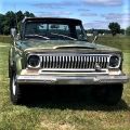
now onto the rest: rebuild the grille, fixed all the front end wiring and mounted the completely refurbished front bumper:
blinkers work, parking lights work, headlights work and the fog lights in the center of the blinkers work. (more than I ever had)
it is all LED and the output is ridiculous.
in the coming weeks I will be working on wiring, which is not my forte so progress will be slow, but it will be precise and neat.
and I'll need to start rebuilding my seats into this:
these are Australian spec seats which had highbacks. the seller of these seats gave me the dimensions so I can rebuild my backrest with seperate headrests to these specifications.
stay tuned, more soon.


Matt
83 Cherokee Laredo WT
L8T 6.6L, 6L90
GEN III LS Swap (LM7 block)
4L60E
83 Cherokee Laredo WT
L8T 6.6L, 6L90
GEN III LS Swap (LM7 block)
4L60E
-
sierrablue
- Posts: 1214
- Joined: Wed Nov 30, 2022 8:02 pm
- Location: MN/CO
Re: wim's '84 blue hemi swap
I'm curious about the headlights too
'71 Wagoneer (DD)
-B350 (HEI, iron 4-barrel, Edelbrock 1406), 700R4, D20
-'74 D44 front (nonpower discs)
-custom headliner
-Front shoulder belts (rears eventually)
viewtopic.php?t=23070
Dec 1962 Panel Delivery
Woods Find
All Original 4x4
-B350 (HEI, iron 4-barrel, Edelbrock 1406), 700R4, D20
-'74 D44 front (nonpower discs)
-custom headliner
-Front shoulder belts (rears eventually)
viewtopic.php?t=23070
Dec 1962 Panel Delivery
Woods Find
All Original 4x4
-
wimsurf
Topic author - Posts: 192
- Joined: Sat Sep 17, 2016 1:22 pm
- Location: Holland
- Contact:
Re: wim's '84 blue hemi swap
I got these, for even less at a European store:
https://www.amazon.com/Newest-Approved- ... B07SC7GK6X
pretty good light output, but not yet sure I like the visual appearance. I might switch to more period correct looking Holley retrobrights, even though they are 400,- before shipping and tax..
1984 grand wagoneer
https://www.fsjnetwork.com/forum/viewto ... 35#p197535
- topaz gold | deep night blue,
- AMC 360 v8 | 2019 5.7 hemi,
- TF727 auto 3 speed | 8hp70 8 speed
- nutmeg interior | sand or almond interior to be decided
https://www.fsjnetwork.com/forum/viewto ... 35#p197535