Page 1 of 1
84 Alternator wires?
Posted: Tue Oct 22, 2019 2:28 pm
by chappys4life
I am working on my 84 Grand Wagoneer with the amc 360. It looks like my alternator just went out last night. After looking at the wiring to the alternator it is a mess.
I see 2 wires
- 1 red wire is on the post of the back of the alternator that goes to a tee that goes to a yellow wire and red wire to the starter relay
- 1 red wire on the side of the alternator using a connector goes to the wire loom for the harness (gets lost in the wire loom)
I want to clean up the wires up as the one on the post has multiple wire butt connectors (4 on the wire leading back to the starter relay

). What is the correct wiring? The engine wiring is all kids of messed up.
Re: 84 Alternator wires?
Posted: Tue Oct 22, 2019 2:39 pm
by fulsizjeep
Welcome to the madness! To be honest, AMC had it's fair share of quirks with wiring. They had 14 years to get it much better by 84 though.
This is a valuable site for a few things:
http://oljeep.com/index.html
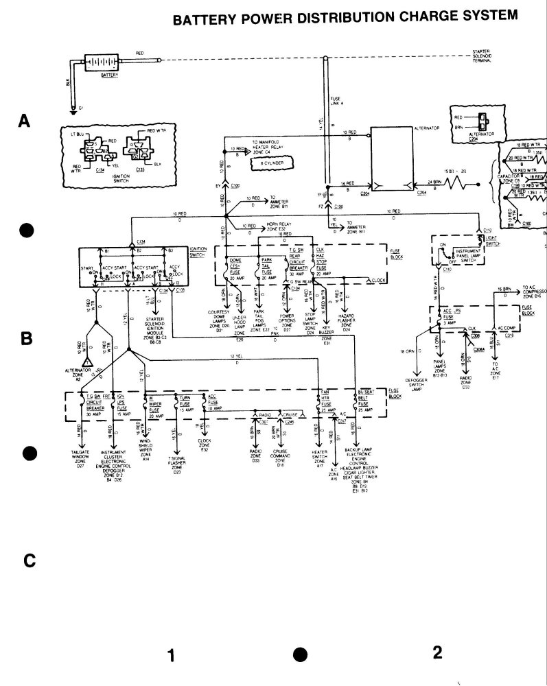
Your alternator connections shown here:
http://oljeep.com/gw/elec/84_85/84_85_F ... mPage1.jpg
Good Luck!
Re: 84 Alternator wires?
Posted: Wed Oct 23, 2019 6:07 am
by tgreese
Mmm. Looking at that diagram, it's quite difficult to understand what the circuit does unless you draw it out on a sheet of paper. Since a 1984 Jeep has an ammeter, it has to have a circuit like the earlier diagrams that are also on that site. You could look at those, if you need some help understanding how the charging circuit is connected. I made this little sketch about how the alternator and ammeter are connected that may help you:
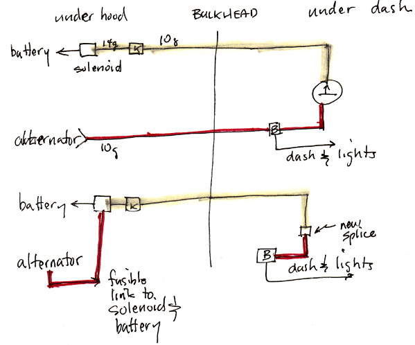
This shows how to bypass the ammeter, but the top half shows how the ammeter circuit works. This is how an ammeter must be wired, though colors and splice names may be different. If your ammeter works, the top diagram is how it must be wired. If the ammeter is gone or does nothing, possible the circuit has been rewired as in the lower half of the diagram.
Note that you need the fusible links in these drawings to protect the Jeep against a fire if the charging circuit shorts out somehow, like in a wreck or whatever. Any short along the original circuit will connect the battery to ground, and then you are protected by the fusible link(s). If you remove the ammeter, you need two fusible links - one in the original location (the 14 ga yellow wire), and one between the alternator and the battery.
Re: 84 Alternator wires?
Posted: Wed Oct 23, 2019 9:49 am
by chappys4life
tgreese wrote: ↑Wed Oct 23, 2019 6:07 am
Mmm. Looking at that diagram, it's quite difficult to understand what the circuit does unless you draw it out on a sheet of paper. Since a 1984 Jeep has an ammeter, it has to have a circuit like the earlier diagrams that are also on that site. You could look at those, if you need some help understanding how the charging circuit is connected. I made this little sketch about how the alternator and ammeter are connected that may help you:
This shows how to bypass the ammeter, but the top half shows how the ammeter circuit works. This is how an ammeter must be wired, though colors and splice names may be different. If your ammeter works, the top diagram is how it must be wired. If the ammeter is gone or does nothing, possible the circuit has been rewired as in the lower half of the diagram.
Note that you need the fusible links in these drawings to protect the Jeep against a fire if the charging circuit shorts out somehow, like in a wreck or whatever. Any short along the original circuit will connect the battery to ground, and then you are protected by the fusible link(s). If you remove the ammeter, you need two fusible links - one in the original location (the 14 ga yellow wire), and one between the alternator and the battery.
**updated with better explanation**
Thank you! This diagram makes it easier to see whats going on. One question though. On your top diagram you show one wire coming off the alternator but I have two coming from mine? I am confused on that part. I did some searching and I think one red wire is for battery charging and the other red wire goes back to the fuse block to be split off for other power.
I am thinking of ditching the ammeter and new alternator. My plan
- Ditch the the yellow wire from for the ammeter (i realize this break the ammeter but I am fine with that)
- Make a red 4 gauge wire from alternator battery post to the solenoid battery side with a 100 amp fuse
- Move red wire (from harness side) that was connected to the alternator battery post to the starer solenoid battery side
- run red wire from 2 wire connector alternator onto the alternator battery post
- It looks like the 2 wire connector is missing a wire on mine (just a red wire), is that ok?
Re: 84 Alternator wires?
Posted: Wed Oct 23, 2019 10:17 am
by tgreese
What's an alternator solenoid? There is a starter solenoid. It sends power to the starter when the key is turned. It also serves as a binding post between the alternator and the battery, and has no role in the charging circuit other than a place to put the wires.
These alternators have three wires. The big red wire is the charging wire. This is the only alternator wire on my diagrams.
The two smaller wires are the voltage sense wire and the exciter wire from the ignition. The exciter sends a tiny current to the alternator when starting to "bootstrap" the alternator into life. Once started, the alternator uses its own voltage to run itself, and the exciter is not needed. The sense wire goes back to the big charge wire to sense the battery voltage. The alternator charge current goes up and down, depending on what battery voltage is sensed.
You cannot use an ammeter unless all the charge current goes through it. If you connect the alternator directly to the battery, replace the ammeter with a voltmeter. Lots written about this here and on the mothership - search.
Re: 84 Alternator wires?
Posted: Wed Oct 23, 2019 10:55 am
by chappys4life
tgreese wrote: ↑Wed Oct 23, 2019 10:17 am
What's an alternator solenoid? There is a starter solenoid. It sends power to the starter when the key is turned. It also serves as a binding post between the alternator and the battery, and has no role in the charging circuit other than a place to put the wires.
These alternators have three wires. The big red wire is the charging wire. This is the only alternator wire on my diagrams.
The two smaller wires are the voltage sense wire and the exciter wire from the ignition. The exciter sends a tiny current to the alternator when starting to "bootstrap" the alternator into life. Once started, the alternator uses its own voltage to run itself, and the exciter is not needed. The sense wire goes back to the big charge wire to sense the battery voltage. The alternator charge current goes up and down, depending on what battery voltage is sensed.
You cannot use an ammeter unless all the charge current goes through it. If you connect the alternator directly to the battery, replace the ammeter with a voltmeter. Lots written about this here and on the mothership - search.
Thank you I corrected my wording in the post. Looks like I want to ditch the ammeter and go with a voltmeter.
Also the two smaller wires - I only have the red wire coming out. Is that a problem?
Re: 84 Alternator wires?
Posted: Wed Oct 23, 2019 11:40 am
by tgreese
These are Delco "unitized" alternators with the regulator built-in to the alternator. From Delco, they have 3 wires - the big wire to a stud on the case and two small wires to the plastic plug. If you search online, there is a lot of information available about these alternators. I can't tell you what you have from here since I don't know the history of the alternator and cannot see what wires are there.
I think you've almost got it, but not quite. There should be a fusible link already in the yellow wire. If so, I would keep the yellow wire to power the dash and lights. Either the red wire or the yellow wire can feed splice B, which is where the fuse panel is powered from. I removed my red wire from the bulkhead connector and ran it over to the solenoid, with a new fusible link in the last few inches of the wire. The original 10 ga wire is plenty big enough for the largest factory alternators, especially when it's such a short distance. A resettable fuse in this line is extra expense, less reliable and overly complex, IMO. Use a fusible link. The only time it would be used is in the event of a catastrophe, like a major wreck. These links are there to prevent the Jeep from burning to the ground because the battery is shorted out. You'll never be in a situation where you'll want to quickly reset one of these links.
Re: 84 Alternator wires?
Posted: Wed Oct 23, 2019 1:06 pm
by chappys4life
Ok thank you I think we are getting somewhere now. My yellow wire is 3 sections with butt connectors so I am afraid they have by passed it. Here is a diagram showing how and proposed changes
