Perfect. I'll do some reading and get this alternator tested. Thank you.tgreese wrote: ↑Mon Aug 07, 2023 10:54 am Yes, the regulator is inside the alternator. These are "SI" alternators: Systems Integrated.
You need three connections - the battery, the sense wire and the exciter wire. If you have the alternator connected right, there is nothing much else you can do. While running, it should maintain the voltage across the battery at something close to 14 volts. This is the electrochemical potential of the lead-acid cells when fully charged of 12.6 volts, plus the voltage across the internal resistance of the battery due to the charging current. 12 volts is too cold (little or no charge current) and 16 volts is too hot (too much charge current, "boiling" the battery).
The TSM has good coverage of the charging system, both theory of operation and diagnosis/repair. Does not have to be the expensive '84 TSM; any of the '80s era books would be fine for this.
TSM.png
Charging Problem
-
AlexJordan22
Topic author - Posts: 74
- Joined: Fri Sep 09, 2022 7:56 am
- Location: Spokane, WA
Re: Charging Problem **SOLVED and then came back :(**
1984 Grand Wagoneer
1979 Mercury Zephyr Z7
1968 Mercury Cougar
2004 F-250
1994 Volvo 850 Wagon
2007 Hyundai Entourage
1979 Mercury Zephyr Z7
1968 Mercury Cougar
2004 F-250
1994 Volvo 850 Wagon
2007 Hyundai Entourage
-
AlexJordan22
Topic author - Posts: 74
- Joined: Fri Sep 09, 2022 7:56 am
- Location: Spokane, WA
Re: Charging Problem **SOLVED and then came back :(**
I got the alternator tested at Napa and it tested good. When I explained the problem the agreed it sounded like the internal voltage regulator was the culprit.
They got me another one but I'm having the same problem, no change. I'll have to read up on the TSM and see what else I need to look at. Just odd it was great with a new alternator and now suddenly it's not.
They got me another one but I'm having the same problem, no change. I'll have to read up on the TSM and see what else I need to look at. Just odd it was great with a new alternator and now suddenly it's not.
1984 Grand Wagoneer
1979 Mercury Zephyr Z7
1968 Mercury Cougar
2004 F-250
1994 Volvo 850 Wagon
2007 Hyundai Entourage
1979 Mercury Zephyr Z7
1968 Mercury Cougar
2004 F-250
1994 Volvo 850 Wagon
2007 Hyundai Entourage
-
 tgreese
- Posts: 7197
- Joined: Fri Jun 08, 2012 6:31 am
- Location: Medford MA USA
Re: Charging Problem **SOLVED and then came back :(**
Is the factory ammeter and wiring still in place?
How are you measuring the voltage? The regulator compares the voltage at the sense wire, terminal 2, to ground potential. The alternator ground is through the brackets and the cast aluminum case. When charging, the voltage you measure between terminal 2 and the case should be the same as what you measure across the battery. That voltage has to be around a volt higher than the normal battery voltage, 12.6 volts. (Each cell is 2.1 volts, and there are six of them in the battery https://en.wikipedia.org/wiki/Lead%E2%80%93acid_battery ).
How are you measuring the voltage? The regulator compares the voltage at the sense wire, terminal 2, to ground potential. The alternator ground is through the brackets and the cast aluminum case. When charging, the voltage you measure between terminal 2 and the case should be the same as what you measure across the battery. That voltage has to be around a volt higher than the normal battery voltage, 12.6 volts. (Each cell is 2.1 volts, and there are six of them in the battery https://en.wikipedia.org/wiki/Lead%E2%80%93acid_battery ).
Tim Reese
Maine beekeeper's truck: '77 J10 LWB, 258/T15/D20/3.54 bone stock, low options (delete radio), PS/PDB, hubcaps.
Browless and proud: '82 J20 360/T18/NP208/3.73, Destination A/Ts, 7600 GVWR
Copper Polly: '75 CJ-6, 304/T15, PS, BFG KM2s, soft top
GTI without the badges: '95 VW Golf Sport 2000cc 2D
Dual Everything: '15 Chryco Jeep Cherokee KL Trailhawk, ECO Green
Blockchain the vote.
-
AlexJordan22
Topic author - Posts: 74
- Joined: Fri Sep 09, 2022 7:56 am
- Location: Spokane, WA
Re: Charging Problem **SOLVED and then came back :(**
Yes, ammeter wiring is all stock.tgreese wrote: ↑Wed Aug 09, 2023 6:39 am Is the factory ammeter and wiring still in place?
How are you measuring the voltage? The regulator compares the voltage at the sense wire to ground potential. The alternator ground is through the brackets and the cast aluminum case. When charging, the voltage you measure between terminal 2 and the case should be the same as what you measure across the battery. That voltage has to be around a volt higher than the normal battery voltage, 12.6 volts. (Each cell is 2.1 volts, and there are six of them in the battery https://en.wikipedia.org/wiki/Lead%E2%80%93acid_battery ).
I will go more in depth tonight and test the ammeter wires and back of the alternator while running to see if I'm losing voltage somewhere along the line. All I did after installing the alternator was test at the battery. I had to wrap things up but still plan to test more tonight and see if I can find a problem.
1984 Grand Wagoneer
1979 Mercury Zephyr Z7
1968 Mercury Cougar
2004 F-250
1994 Volvo 850 Wagon
2007 Hyundai Entourage
1979 Mercury Zephyr Z7
1968 Mercury Cougar
2004 F-250
1994 Volvo 850 Wagon
2007 Hyundai Entourage
-
tgreese
- Posts: 7197
- Joined: Fri Jun 08, 2012 6:31 am
- Location: Medford MA USA
Re: Charging Problem **SOLVED and then came back :(**
The only way the ammeter wiring could affect the charge voltage is if the sense wire is reading the battery voltage plus the voltage drop across the ammeter. The earlier diagrams I looked at for the Delco alternator are not wired that way, and it would be kinda dumb to do that IMO. Instead, the sense wire goes from the alternator to the starter solenoid, which is for all intents and purposes the battery voltage.
You understand what I am getting at? Resistances in series make a voltage divider. One would not want to include that divider in the sense voltage circuit. You want 13.5 volts across the battery, not across the battery plus ammeter. The wiring should have negligible resistance in all cases. It's not meant to be part of the circuit, and it mostly isn't until it goes bad. However, putting the ammeter wiring between the sense wire and the battery creates a liability if that part of the circuit goes bad.
Dunno, maybe that's how they do it in the later vehicles. Including the ammeter resistance in the sense voltage would prevent the catastrophic dash fire that can occur with these ammeters. Ammeter resistance would go up and current would drop. The battery would go flat, but you would not have a fire. Maybe.
Suggest you measure the voltages as I suggested. I presume you have a good multimeter.
You can trace out the wires from the '84 diagram on the Tom Collins site and see where the sense wire connects. I predict when you unwind the drawing, the sense wire connects to the battery, not to the alternator side of the ammeter. The schematics are on a few pages and I did not study them very carefully - that's something I suggest you should do.
Tim Reese
Maine beekeeper's truck: '77 J10 LWB, 258/T15/D20/3.54 bone stock, low options (delete radio), PS/PDB, hubcaps.
Browless and proud: '82 J20 360/T18/NP208/3.73, Destination A/Ts, 7600 GVWR
Copper Polly: '75 CJ-6, 304/T15, PS, BFG KM2s, soft top
GTI without the badges: '95 VW Golf Sport 2000cc 2D
Dual Everything: '15 Chryco Jeep Cherokee KL Trailhawk, ECO Green
Blockchain the vote.
Maine beekeeper's truck: '77 J10 LWB, 258/T15/D20/3.54 bone stock, low options (delete radio), PS/PDB, hubcaps.
Browless and proud: '82 J20 360/T18/NP208/3.73, Destination A/Ts, 7600 GVWR
Copper Polly: '75 CJ-6, 304/T15, PS, BFG KM2s, soft top
GTI without the badges: '95 VW Golf Sport 2000cc 2D
Dual Everything: '15 Chryco Jeep Cherokee KL Trailhawk, ECO Green
Blockchain the vote.
-
AlexJordan22
Topic author - Posts: 74
- Joined: Fri Sep 09, 2022 7:56 am
- Location: Spokane, WA
Re: Charging Problem **SOLVED and then came back :(**
Red wire on the back of the alternator is showing 13.4.
Battery terminals (and cables themselves) are showing 12.6.
Yellow wire on solenoid and negative battery - 12.6.
Yellow wire on solenoid and alternator body - 12.6.
On the two-wire plug that goes to the side of the alternator - red wire shows 12.0 and brown wire showing 8.4V.
The red wire on the back stud of the alternator should be reading the same as the yellow wire going to the solenoid but it isn't.
1984 Grand Wagoneer
1979 Mercury Zephyr Z7
1968 Mercury Cougar
2004 F-250
1994 Volvo 850 Wagon
2007 Hyundai Entourage
1979 Mercury Zephyr Z7
1968 Mercury Cougar
2004 F-250
1994 Volvo 850 Wagon
2007 Hyundai Entourage
-
tgreese
- Posts: 7197
- Joined: Fri Jun 08, 2012 6:31 am
- Location: Medford MA USA
Re: Charging Problem **SOLVED and then came back :(**
Where are you testing ground? Do you get different readings if you test between the case and the negative battery terminal? I would test all three alternator wires to the case and to battery ground. 13.4 coming from the alternator is about right, but I would expect it to be the same as the other two terminals when compared to ground at the case. The brown wire is connected to the ignition switch, and normally is driven high by the alternator (full output voltage) when the alternator is charging. 8.4 volts seems quite low. This is with the engine running at say 1500 RPM? What do you measure at the brown wire with the engine off?
Tim Reese
Maine beekeeper's truck: '77 J10 LWB, 258/T15/D20/3.54 bone stock, low options (delete radio), PS/PDB, hubcaps.
Browless and proud: '82 J20 360/T18/NP208/3.73, Destination A/Ts, 7600 GVWR
Copper Polly: '75 CJ-6, 304/T15, PS, BFG KM2s, soft top
GTI without the badges: '95 VW Golf Sport 2000cc 2D
Dual Everything: '15 Chryco Jeep Cherokee KL Trailhawk, ECO Green
Blockchain the vote.
Maine beekeeper's truck: '77 J10 LWB, 258/T15/D20/3.54 bone stock, low options (delete radio), PS/PDB, hubcaps.
Browless and proud: '82 J20 360/T18/NP208/3.73, Destination A/Ts, 7600 GVWR
Copper Polly: '75 CJ-6, 304/T15, PS, BFG KM2s, soft top
GTI without the badges: '95 VW Golf Sport 2000cc 2D
Dual Everything: '15 Chryco Jeep Cherokee KL Trailhawk, ECO Green
Blockchain the vote.
-
letank
- Posts: 4030
- Joined: Wed Oct 03, 2012 9:16 pm
- Location: SF bay area
Re: Charging Problem **SOLVED and then came back :(**
As Tim suggested, time to do the ammeter bypass to prevent JeepBBQ.
Quick references here:
viewtopic.php?t=16778
DIsconnect battery first, I did the Stuka's way, connect both wires at the ammeter to one post of the ammeter.
You can always wire a 12 or 10 gauge from the battery + Post to the Alt + post and add a slow blow fuse 150 amp is what I have.
May be a little rust somewhere
You do not have the required permissions to view the files attached to this post.
Michel
74 wag (349 Kmiles... parked, next step is a rust free body)
85 Gwag (229 Kmiles... the running test lab)
74 wag (349 Kmiles... parked, next step is a rust free body)
85 Gwag (229 Kmiles... the running test lab)
-
AlexJordan22
Topic author - Posts: 74
- Joined: Fri Sep 09, 2022 7:56 am
- Location: Spokane, WA
Re: Charging Problem **SOLVED and then came back :(**
So if I connect both wires to one post at the ammeter, I'm assuming I won't have a working ammeter anymore correct? Are the two ways to do this either to connect them both at the ammeter; or remove those wires completely and just run one wire from the alternator to the battery (or positive post of the solenoid as the yellow wire from the ammeter currently is?letank wrote: ↑Wed Aug 09, 2023 4:47 pm As Tim suggested, time to do the ammeter bypass to prevent JeepBBQ.
Quick references here:
viewtopic.php?t=16778
DIsconnect battery first, I did the Stuka's way, connect both wires at the ammeter to one post of the ammeter.
You can always wire a 12 or 10 gauge from the battery + Post to the Alt + post and add a slow blow fuse 150 amp is what I have.
May be a little rust somewhere
AltPost2x.jpg
1984 Grand Wagoneer
1979 Mercury Zephyr Z7
1968 Mercury Cougar
2004 F-250
1994 Volvo 850 Wagon
2007 Hyundai Entourage
1979 Mercury Zephyr Z7
1968 Mercury Cougar
2004 F-250
1994 Volvo 850 Wagon
2007 Hyundai Entourage
-
AlexJordan22
Topic author - Posts: 74
- Joined: Fri Sep 09, 2022 7:56 am
- Location: Spokane, WA
Re: Charging Problem **SOLVED and then came back :(**
I did a search. I think I will remove the current red wire from the back of the alternator and the wiring block at the firewall, and then add a new 10 gauge wire from the alternator to the battery side of the solenoid with a 14 gauge fusible link as tgreese suggested in another thread. Sounds easy enough.
1984 Grand Wagoneer
1979 Mercury Zephyr Z7
1968 Mercury Cougar
2004 F-250
1994 Volvo 850 Wagon
2007 Hyundai Entourage
1979 Mercury Zephyr Z7
1968 Mercury Cougar
2004 F-250
1994 Volvo 850 Wagon
2007 Hyundai Entourage
-
tgreese
- Posts: 7197
- Joined: Fri Jun 08, 2012 6:31 am
- Location: Medford MA USA
Re: Charging Problem **SOLVED and then came back :(**
Yes, if you connect two posts together at the ammeter, the ammeter does not work.
I made this drawing that may help:
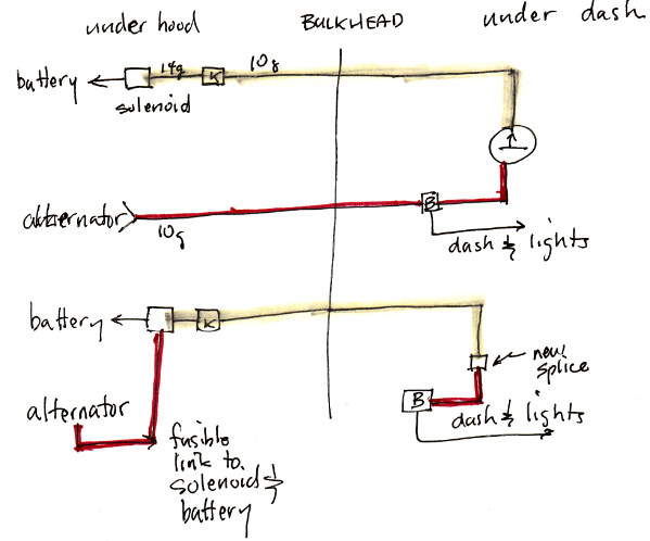
Top is the factory config, below is converted. "Bulkhead" is the big connector that goes through the firewall. The 14 ga wire is the single existing fusible link. The letters K and B are factory splices; the colors and letters are correct for my '82 wiring diagram. I unplugged the red wire from the bulkhead connector and used it to run to the battery, with an added 14 ga fusible link at the solenoid end. Not shown, but I abandoned in place the red wire from splice B to the bulkhead.
On the Jeeps with a voltmeter ('76 and up CJ, for example) the "2" sense wire is only a few inches long and immediately connects back to the alternator battery terminal.
There is a locked thread on IFSJA with nothing but discussion of this topic. Not sure it's worth reading all the threads there; everybody has a slightly different take, which they express with certainty.
I made this drawing that may help:
Top is the factory config, below is converted. "Bulkhead" is the big connector that goes through the firewall. The 14 ga wire is the single existing fusible link. The letters K and B are factory splices; the colors and letters are correct for my '82 wiring diagram. I unplugged the red wire from the bulkhead connector and used it to run to the battery, with an added 14 ga fusible link at the solenoid end. Not shown, but I abandoned in place the red wire from splice B to the bulkhead.
On the Jeeps with a voltmeter ('76 and up CJ, for example) the "2" sense wire is only a few inches long and immediately connects back to the alternator battery terminal.
There is a locked thread on IFSJA with nothing but discussion of this topic. Not sure it's worth reading all the threads there; everybody has a slightly different take, which they express with certainty.
Tim Reese
Maine beekeeper's truck: '77 J10 LWB, 258/T15/D20/3.54 bone stock, low options (delete radio), PS/PDB, hubcaps.
Browless and proud: '82 J20 360/T18/NP208/3.73, Destination A/Ts, 7600 GVWR
Copper Polly: '75 CJ-6, 304/T15, PS, BFG KM2s, soft top
GTI without the badges: '95 VW Golf Sport 2000cc 2D
Dual Everything: '15 Chryco Jeep Cherokee KL Trailhawk, ECO Green
Blockchain the vote.
Maine beekeeper's truck: '77 J10 LWB, 258/T15/D20/3.54 bone stock, low options (delete radio), PS/PDB, hubcaps.
Browless and proud: '82 J20 360/T18/NP208/3.73, Destination A/Ts, 7600 GVWR
Copper Polly: '75 CJ-6, 304/T15, PS, BFG KM2s, soft top
GTI without the badges: '95 VW Golf Sport 2000cc 2D
Dual Everything: '15 Chryco Jeep Cherokee KL Trailhawk, ECO Green
Blockchain the vote.
-
AlexJordan22
Topic author - Posts: 74
- Joined: Fri Sep 09, 2022 7:56 am
- Location: Spokane, WA
Re: Charging Problem **SOLVED and then came back :(**
The way you have it laid out is how I picture it too. Use the existing red wire to instead go to the solenoid and just add a fusible link to it. Simple enough and will be much safer. Thanks for the drawing
1984 Grand Wagoneer
1979 Mercury Zephyr Z7
1968 Mercury Cougar
2004 F-250
1994 Volvo 850 Wagon
2007 Hyundai Entourage
1979 Mercury Zephyr Z7
1968 Mercury Cougar
2004 F-250
1994 Volvo 850 Wagon
2007 Hyundai Entourage
-
tgreese
- Posts: 7197
- Joined: Fri Jun 08, 2012 6:31 am
- Location: Medford MA USA
Re: Charging Problem **SOLVED and then came back :(**
NP - I had the drawing - posted it a bunch of times! 
Tim Reese
Maine beekeeper's truck: '77 J10 LWB, 258/T15/D20/3.54 bone stock, low options (delete radio), PS/PDB, hubcaps.
Browless and proud: '82 J20 360/T18/NP208/3.73, Destination A/Ts, 7600 GVWR
Copper Polly: '75 CJ-6, 304/T15, PS, BFG KM2s, soft top
GTI without the badges: '95 VW Golf Sport 2000cc 2D
Dual Everything: '15 Chryco Jeep Cherokee KL Trailhawk, ECO Green
Blockchain the vote.
Maine beekeeper's truck: '77 J10 LWB, 258/T15/D20/3.54 bone stock, low options (delete radio), PS/PDB, hubcaps.
Browless and proud: '82 J20 360/T18/NP208/3.73, Destination A/Ts, 7600 GVWR
Copper Polly: '75 CJ-6, 304/T15, PS, BFG KM2s, soft top
GTI without the badges: '95 VW Golf Sport 2000cc 2D
Dual Everything: '15 Chryco Jeep Cherokee KL Trailhawk, ECO Green
Blockchain the vote.
-
AlexJordan22
Topic author - Posts: 74
- Joined: Fri Sep 09, 2022 7:56 am
- Location: Spokane, WA
Re: Charging Problem **SOLVED and then came back :(**
I must be missing something. I bypassed my ammeter as shown. 10ga red wire from back of alternator to the battery side of solenoid with a 14ga fusible link.
Now the alternator is putting out 12.6V when measured at the back of the alternator and ground anywhere else. The case, negative battery, body ground, etc they all read the same.
The small red wire gets 12.6V and the brown wire is getting 8-9V fluctuating. I used different grounds when testing and got these readings. I may have to have this alternator tested now too, because it was putting out 13+ on the back of the alternator before and nothing changed except where that red wire goes to.
1984 Grand Wagoneer
1979 Mercury Zephyr Z7
1968 Mercury Cougar
2004 F-250
1994 Volvo 850 Wagon
2007 Hyundai Entourage
1979 Mercury Zephyr Z7
1968 Mercury Cougar
2004 F-250
1994 Volvo 850 Wagon
2007 Hyundai Entourage
-
tgreese
- Posts: 7197
- Joined: Fri Jun 08, 2012 6:31 am
- Location: Medford MA USA
Re: Charging Problem **SOLVED and then came back :(**
The big red wire goes to the battery cable on the solenoid - directly to the battery positive post. The small red wire goes to the big red wire - this is the voltage feedback. The brown wire goes to the ignition switch.
The brown wire gives a trickle of current to the alternator at start up. After starting, the alternator is charging and holds the brown wire at its full output voltage - there should be no current in the brown wire when the alternator is running. If the brown wire is at 8 volts at the alternator and 12.6 volts at the ignition switch, that's a voltage difference of 4.6 volts through 15 ohms, I = V/R is about 300 ma. Seems like a lot ... I would expect the alternator to hold the brown wire at close to the battery voltage.
You can substitute an incandescent bulb for the brown wire and see if it lights. This is how my J20 is wired now, with an ALT light. If the alternator is working right, that bulb should be lit when the engine is off and the key is on. Ignition switch sources current, alternator sinks current, bulb lights. The bulb should go out when the engine is started; the brown wire is now at 12V at both ends, and no current flows. Both ends become sources. 300 ma seems like plenty to light a bulb, and if the ALT light were on with the engine running, that means the alternator is not working.
The resistance of either the bulb or the resistance wire is high enough so when you turn the key off, there is not enough current to backfeed into the ignition switch and keep the engine running. Substitute a plain wire for the resistance wire to see this effect - and be ready to disconnect it when you want to shut the engine off.
Tim Reese
Maine beekeeper's truck: '77 J10 LWB, 258/T15/D20/3.54 bone stock, low options (delete radio), PS/PDB, hubcaps.
Browless and proud: '82 J20 360/T18/NP208/3.73, Destination A/Ts, 7600 GVWR
Copper Polly: '75 CJ-6, 304/T15, PS, BFG KM2s, soft top
GTI without the badges: '95 VW Golf Sport 2000cc 2D
Dual Everything: '15 Chryco Jeep Cherokee KL Trailhawk, ECO Green
Blockchain the vote.
Maine beekeeper's truck: '77 J10 LWB, 258/T15/D20/3.54 bone stock, low options (delete radio), PS/PDB, hubcaps.
Browless and proud: '82 J20 360/T18/NP208/3.73, Destination A/Ts, 7600 GVWR
Copper Polly: '75 CJ-6, 304/T15, PS, BFG KM2s, soft top
GTI without the badges: '95 VW Golf Sport 2000cc 2D
Dual Everything: '15 Chryco Jeep Cherokee KL Trailhawk, ECO Green
Blockchain the vote.
-
AlexJordan22
Topic author - Posts: 74
- Joined: Fri Sep 09, 2022 7:56 am
- Location: Spokane, WA
Re: Charging Problem **SOLVED and then came back :(**
I checked those voltages with the small red & brown wires unplugged from the alternator. I should have checked them while they were plugged in but didn't. I printed off the wiring diagram and read the charging section of the manual you linked prior.tgreese wrote: ↑Tue Aug 15, 2023 11:17 am The big red wire goes to the battery cable on the solenoid - directly to the battery positive post. The small red wire goes to the big red wire - this is the voltage feedback. The brown wire goes to the ignition switch.
The brown wire gives a trickle of current to the alternator at start up. After starting, the alternator is charging and holds the brown wire at its full output voltage - there should be no current in the brown wire when the alternator is running. If the brown wire is at 8 volts at the alternator and 12.6 volts at the ignition switch, that's a voltage difference of 4.6 volts through 15 ohms, I = V/R is about 300 ma. Seems like a lot ... I would expect the alternator to hold the brown wire at close to the battery voltage.
You can substitute an incandescent bulb for the brown wire and see if it lights. This is how my J20 is wired now, with an ALT light. If the alternator is working right, that bulb should be lit when the engine is off and the key is on. Ignition switch sources current, alternator sinks current, bulb lights. The bulb should go out when the engine is started; the brown wire is now at 12V at both ends, and no current flows. Both ends become sources. 300 ma seems like plenty to light a bulb, and if the ALT light were on with the engine running, that means the alternator is not working.
The resistance of either the bulb or the resistance wire is high enough so when you turn the key off, there is not enough current to backfeed into the ignition switch and keep the engine running. Substitute a plain wire for the resistance wire to see this effect - and be ready to disconnect it when you want to shut the engine off.
I did see the note in there that states the alternator may not show a charge if the battery is depleted. My battery has been low since this issue began but I don't know if it was low enough for the alternator to just not charge. Seems like probably not, but it caught my attention.
You do not have the required permissions to view the files attached to this post.
1984 Grand Wagoneer
1979 Mercury Zephyr Z7
1968 Mercury Cougar
2004 F-250
1994 Volvo 850 Wagon
2007 Hyundai Entourage
1979 Mercury Zephyr Z7
1968 Mercury Cougar
2004 F-250
1994 Volvo 850 Wagon
2007 Hyundai Entourage
-
tgreese
- Posts: 7197
- Joined: Fri Jun 08, 2012 6:31 am
- Location: Medford MA USA
Re: Charging Problem **SOLVED and then came back :(**
Well, the small red wire connects to the big red wire now, so they should read the same. You can prove it to yourself by testing continuity between the red wires with the key off. Without the small red wire connected, there is no voltage feedback and the alternator does nothing. Then both red wires will read the battery voltage, whatever that is.
If you measure the brown wire with it disconnected from the alternator, it should read whatever voltage you have at the ignition switch. Connected to nothing is called "floating" - that is, not a circuit. With the connection floating, the only load is the input impedance of your meter which should be very very very high and a negligible load. You should see no voltage drop between the ignition switch and the floating connector.
They are referring to the alternator "bootstrap" at startup where the alternator uses a trickle of battery current to make its own current to make more current. Once started, the alternator feeds itself from its output. You need to get that started with a little current from the battery, typically. Even the residual magnetism in the iron can make this trickle if you spin the alternator fast enough.
Completely discharge means really flat. Even when your battery is too dead to run the lights or starter, there is enough current to bootstrap the alternator.
Tim Reese
Maine beekeeper's truck: '77 J10 LWB, 258/T15/D20/3.54 bone stock, low options (delete radio), PS/PDB, hubcaps.
Browless and proud: '82 J20 360/T18/NP208/3.73, Destination A/Ts, 7600 GVWR
Copper Polly: '75 CJ-6, 304/T15, PS, BFG KM2s, soft top
GTI without the badges: '95 VW Golf Sport 2000cc 2D
Dual Everything: '15 Chryco Jeep Cherokee KL Trailhawk, ECO Green
Blockchain the vote.
Maine beekeeper's truck: '77 J10 LWB, 258/T15/D20/3.54 bone stock, low options (delete radio), PS/PDB, hubcaps.
Browless and proud: '82 J20 360/T18/NP208/3.73, Destination A/Ts, 7600 GVWR
Copper Polly: '75 CJ-6, 304/T15, PS, BFG KM2s, soft top
GTI without the badges: '95 VW Golf Sport 2000cc 2D
Dual Everything: '15 Chryco Jeep Cherokee KL Trailhawk, ECO Green
Blockchain the vote.
-
AlexJordan22
Topic author - Posts: 74
- Joined: Fri Sep 09, 2022 7:56 am
- Location: Spokane, WA
Re: Charging Problem **SOLVED and then came back :(**
I guess I don't know what else to do besides get this alternator tested. I don't think that's the issue, but I guess it's possible.
1984 Grand Wagoneer
1979 Mercury Zephyr Z7
1968 Mercury Cougar
2004 F-250
1994 Volvo 850 Wagon
2007 Hyundai Entourage
1979 Mercury Zephyr Z7
1968 Mercury Cougar
2004 F-250
1994 Volvo 850 Wagon
2007 Hyundai Entourage
-
letank
- Posts: 4030
- Joined: Wed Oct 03, 2012 9:16 pm
- Location: SF bay area
Re: Charging Problem **SOLVED and then came back :(**
May be have the alternator tested at 2 different places.
Otherwise make sure that your voltmeter is giving you the real data, that it is accurate! Devices degrade with time.
Otherwise make sure that your voltmeter is giving you the real data, that it is accurate! Devices degrade with time.
Michel
74 wag (349 Kmiles... parked, next step is a rust free body)
85 Gwag (229 Kmiles... the running test lab)
74 wag (349 Kmiles... parked, next step is a rust free body)
85 Gwag (229 Kmiles... the running test lab)
-
tgreese
- Posts: 7197
- Joined: Fri Jun 08, 2012 6:31 am
- Location: Medford MA USA
Re: Charging Problem **SOLVED and then came back :(**
Suggestion - go back through the thread and read it all again, in detail. There's a lot there about how the charging circuit works. If you read the TSM again and have questions about that, I would be happy to answer. It'll be work - harder than reading a magazine or such - take notes if that helps.
You know what they say - "you had to be there." For all but the easiest questions, you need the Jeep in front of you to solve electrical problems. Once you understand how it's supposed to work, you can draw out the circuit and measure voltages and hopefully the problem will become clear.
Sorry to say, I think it's more likely that the alternator is ok and something is messed up with connecting it to the Jeep. Did the store use a dynamic tester, ie they spin the alternator and see what voltage it makes? However, you don't need the store to test the alternator. You can unplug the small connector and connect both leads to the battery terminal, and the alternator should charge. Go back and read about the circuit and convince yourself this should be so.
You could use a couple of push-on connectors and some wire, or some clip leads. Clip leads are a handy thing to have, regardless. https://www.amazon.com/clip-leads/s?k=clip+leads
Or, you could give up and buy a one-wire 10SI alternator and use that. Then you'll only have the battery wire.
Tim Reese
Maine beekeeper's truck: '77 J10 LWB, 258/T15/D20/3.54 bone stock, low options (delete radio), PS/PDB, hubcaps.
Browless and proud: '82 J20 360/T18/NP208/3.73, Destination A/Ts, 7600 GVWR
Copper Polly: '75 CJ-6, 304/T15, PS, BFG KM2s, soft top
GTI without the badges: '95 VW Golf Sport 2000cc 2D
Dual Everything: '15 Chryco Jeep Cherokee KL Trailhawk, ECO Green
Blockchain the vote.
Maine beekeeper's truck: '77 J10 LWB, 258/T15/D20/3.54 bone stock, low options (delete radio), PS/PDB, hubcaps.
Browless and proud: '82 J20 360/T18/NP208/3.73, Destination A/Ts, 7600 GVWR
Copper Polly: '75 CJ-6, 304/T15, PS, BFG KM2s, soft top
GTI without the badges: '95 VW Golf Sport 2000cc 2D
Dual Everything: '15 Chryco Jeep Cherokee KL Trailhawk, ECO Green
Blockchain the vote.