Tutorial to trouble shoot cruise control system

Stock FSJ Tech Area
Post Reply

Topic author
PaulD
Posts: 48
Joined: Sat Jul 15, 2017 11:12 am
Location: Arkansas

Tutorial to trouble shoot cruise control system

Post by PaulD »

With my 89 GW cruise control not working and no official system tester (AM P-C-1R tester) in hand, I started trying to trouble shoot the system. Major pains since some of the components and connections that need testing are under the dash and can be hard to get to. I then realized that the P-C-1R tester works by removing the control module (in yellow box under dash passenger side) and then plugging the tester into the 14 pin connector where the control had been plugged in. By studying the wiring diagram in the service manual, it is easy to see multiple test that can be performed at this connector since it touches all components in the system. I then started checking pin reading for proper ohms, VDC and VAC reading. In that way, I discovered that my cruise control module was not receiving the proper 12VDC on pin 7. Without that power, the module was dead. I traced down the problem (bad connection to fuse panel) and got power back to the module. Happily, my cruise control is back in business.
Manually testing via the 14 pin connector is not hard but it can be tedious. To help others trouble shoot problems with their cruise control, I have prepared the following tutorial on testing the cruise control system. Note that this is based on an 89 GW. Your FSJ system may be different but the principles are the same. Refer to the wiring diagrams in your FSJ to help work out any difference.

For starters, let’s take a quick look at the main components in the system.
1) Control module – circuit card in a yellow box under dash. My yellow box was under dash next to left foot of passenger. This testing does not test the module. It tests everything BUT the module. If everything else test OK then that implies that the module is bad.
2) Multi-function lever on steering column – inputs commands to system for setting and adjusting speeds
3) Brake control switch – mounted above the brake petal. It is an open circuit until you hit the brakes then it allows 12VDC to flow to the module on pin 13. The module monitors pin 13 to know when you applied brakes so it can turn cruise off when you apply the brakes
4) Inline 4 amp glass fuse that feeds 12VDC to the multi-function lever. I think it is a slow blow fuse but not sure. If blown, nothing will work. Impacts reading on pins 5, 10 and 14. This fuse is buried deep under dash and very difficult to get to.
5) Speed sensor – sensor mounted to transmission and lets module know your speed. Inputs to the module via pins 2 and 3. Voltage readings are AC (not DC). That tells me that the sensor is a small motor (generator) that generates a variable VAC depending on speed.
6) Control servo – Mounted on driver side fender under hood. Uses vacuum and signals from cruise module to control gas to carburetor. Linked to cruise module via pins 4, 6, 11 and 12
7) Fuse panel – mid left side of panel has a slot (marked for cruise control) to plug the cruise control power wire into. The plug gets it power from the yellow 20 amp HAZ/STOP fuse. This power wire goes to pin 7 in the 14 pin connector
8) Ignition key – position of ignition key is important in the testing since the cruise control system is like an accessory and only works when key is in RUN position
9) Connectors and connections – even if all components are good, a bad connection is very possible and will cause bad or erratic readings. Always tough to track down the specific bad spot.

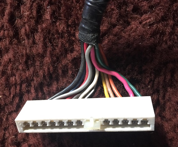
Recap of the 14 pins in the connector shown below. Pins numbered 1-14 from left to right.
1 – Ground wire
2 – Speed sensor and Cruise control servo
3 – Speed sensor
4 – Cruise control servo
5 –Multi-function lever
6 - Cruise control servo
7 – 12VDC from fuse box
8 – Unused
9 – Unused
10 - Multi-function lever
11 - Cruise control servo
12 - Cruise control servo
13 – Brake switch
14 - Multi-function lever

Image

The following test are grouped by type of test. All tests are done with a simple VOM meter that can measure ohms, VDC and VAC. These tests are electrical in nature only. Does not test your vacuum (must be OK for control servo to function) and the linkage to the carb (properly adjusted). All these test will do is point you to the circuit that has a problem. You will probably need to do addition testing to isolate the problem in a bad circuit.
Last edited by PaulD on Wed Aug 16, 2017 9:31 am, edited 2 times in total.

Topic author
PaulD
Posts: 48
Joined: Sat Jul 15, 2017 11:12 am
Location: Arkansas

Re: Tutorial to trouble shoot cruise control system

Post by PaulD »

Ohms test
Not all pins provide a meaningful ohms reading. Start by attaching your black lead to a solid ground point (not pin 1). Use the red lead to probe the pin noted below.
With Key OFF and cruise switch OFF:
Pin 1 – CLOSED – since this pin is supposed to be a ground for the module, this pin should show closed circuit
Pins 2-3 – no test at this point
Pins 4-7 and 10-14 should show OPEN. If not, something in circuit it shorted to ground.
Now remove the black lead from its grounding point and use the red and black leads to measure ohms between pins 2 and 3. Should read between 15-50 ohms.
Now use black and red leads to measure ohms between pins 2 and 11 while engine is running. Should read from 240 to 4K ohms as you advance throttle from idle to full throttle.

Topic author
PaulD
Posts: 48
Joined: Sat Jul 15, 2017 11:12 am
Location: Arkansas

Re: Tutorial to trouble shoot cruise control system

Post by PaulD »

VDC test
This is a DC voltage test with red probe while black probe is attached to good ground. Key and cruise switch position varies as noted below.

Pin 1 - Zero volts with key on or off – if not, it is shorted to 12V somewhere
Pin 2 & 3 – Should not have any DC current in either pin. If you do, the wires are shorted to a DC source somewhere. See AC test later for proper AC voltage test on these pins
Pin 4 – No test identified
Pin 5 – 0 VDC (Key ON/Cruise OFF)
12VDC (Key ON/Cruise ON)
12VDC (Key OK/Cruise RA)
Pin 6 - No test identified
Pin 7 - 12VDC all time. The current flows through the 20 amp HAZ/STOP over to the Cruise Control connect point. If no power, problem could be blown HAZ/STOP fuse or bad connection. If Hazard lights work OK then fuse is good.
Pin 8 - Unused
Pin 9 - Unused
Pin 10 - 12VDC (Key ON/Cruise RA)
0 VDC (any other key or cruise position)
Pin 11 - No test identified
Pin 12 - No test identified
Pin 13 - 0 VDC (Key ON/Brake OFF)
12VDC (Key ON/Brake ON). If no power, the problem involves the brake light switch circuit. If brake lights work but no power, then problem is in the connection or line from brake light switch to pin 13.
Pin 14 – 0 VDC (Key ON/Cruise OFF)
0 VDC (Key ON/Cruise ON)
12VDC (Key ON/Cruise set ON via push button on end of lever)
Last edited by PaulD on Wed Aug 16, 2017 9:41 am, edited 1 time in total.

Topic author
PaulD
Posts: 48
Joined: Sat Jul 15, 2017 11:12 am
Location: Arkansas

Re: Tutorial to trouble shoot cruise control system

Post by PaulD »

VAC test
This is an AC voltage test while vehicle moving or on lift with rear wheels free to turn. This test is only for the speed sensor thus only involves pins 2 and 3. The speed sensor is a small A/C motor that generates current when driving. The A/C current varies according to speed
Ignition; ON with motor running
Gear: Drive
Cruise switch : ON
Test VAC reading between pins 2 and 3 starting at 30 MPH. Should get a 0.9VAC reading at 30 MPH and increase 0.1VDC for each 10 MPH.

Topic author
PaulD
Posts: 48
Joined: Sat Jul 15, 2017 11:12 am
Location: Arkansas

Re: Tutorial to trouble shoot cruise control system

Post by PaulD »

Other test
1) With engine running, transmission in park and cruise control ON, advancing speed via the R/A switch should cause engine RPM to increase
2) With key on, inserting a jumper wire between pins 7 and 13 should cause brake lights to come on. This is effectively bypassing the brake switch.
3) Service manual has a bunch of test and procedures for adjusting the cruise control module itself. They are designed to set various adjustments on a working module. I did not try to address any that here.

Topic author
PaulD
Posts: 48
Joined: Sat Jul 15, 2017 11:12 am
Location: Arkansas

Re: Tutorial to trouble shoot cruise control system

Post by PaulD »

That is all I have for now. If I discover any more useable test, I will post them here. If anyone discovers an error in my info, let me know.
User avatar

BaldBeardedBastard
Posts: 168
Joined: Fri Jan 29, 2016 2:52 pm

Re: Tutorial to trouble shoot cruise control system

Post by BaldBeardedBastard »

Great work instruction! I will go through it next weekend and hopefully I will have cruise control again. Thanks for the write up


Sent from my iPhone using Tapatalk
'86 GW Cummins 2.8/4l60E. Hopefully bouncing down a dusty road somewhere.
Build Thread
User avatar

dodgerammit
Posts: 1438
Joined: Wed Jan 11, 2017 11:20 pm
Location: Middle TN

Re: Tutorial to trouble shoot cruise control system

Post by dodgerammit »

Nice. I copied and pasted into a text sheet for later use. Thanks!
84 Grand Waggy-Radio Flyer (Garnet Red/3M Ebony Metallic woodgrain, with honey interior) AMC 360 :cry: 2004 4.8LS/Advance Adapter/727/242 D44/AMC20 Serehill tailgate and headlight harnesses :fsj: Ongoing thread-viewtopic.php?t=11897

92 Wrangler Islander 4.0/32RH/231 D30/D35 RHD
User avatar

jsinajeep
Posts: 1850
Joined: Tue Aug 23, 2011 8:25 pm
Location: Brownsburg Indiana

Re: Tutorial to trouble shoot cruise control system

Post by jsinajeep »

Very good write up PaulD

Topic author
PaulD
Posts: 48
Joined: Sat Jul 15, 2017 11:12 am
Location: Arkansas

Re: Tutorial to trouble shoot cruise control system

Post by PaulD »

I would like to know if anyone used these test and got their cruise control back working. Would make all my work more rewarding.
User avatar

wimsurf
Posts: 191
Joined: Sat Sep 17, 2016 1:22 pm
Location: Holland
Contact:

Re: Tutorial to trouble shoot cruise control system

Post by wimsurf »

hi Paul, I did your tests to verify that my CC electronics are in good order. I narrowed my issues down to the servo under the hood now. thanks so much for this write up!
1984 grand wagoneer
  • topaz gold | deep night blue,
  • AMC 360 v8 | 2019 5.7 hemi,
  • TF727 auto 3 speed | 8hp70 8 speed
  • nutmeg interior | sand or almond interior to be decided
it's a project now:
https://www.fsjnetwork.com/forum/viewto ... 35#p197535
User avatar

Rinkle_Stinkle
Posts: 224
Joined: Thu Nov 16, 2017 9:22 am

Re: Tutorial to trouble shoot cruise control system

Post by Rinkle_Stinkle »

I can't wait to diagnose my cruise control! now if I can just figure out how to use my Greenlee meter haha... (Electricity is not my forte, actually not a lot is tbh)

I know I have good VAC because I disconnected a line the other day and heard the pressure release, so I'm thinking electrical.

Question: and excuse me ignorance but what does "Cruise RA" stand for?
1988 Grand Wag
AMC 360 with 96K
Edelbrock intake manifold
260H Comp Cam
Edelbrock AVS 4brl carb
Headman headers
2" to thrush muff with 3" tip exhaust
User avatar

Greg72
Posts: 84
Joined: Mon Aug 14, 2023 10:52 am

Re: Tutorial to trouble shoot cruise control system

Post by Greg72 »

Nice Writeup!!!

Thank you for putting in the time to do this. Bookmarking this for future use.


-G
1989 Jeep Grand Wagoneer - !! NEW !!

will e
Posts: 5103
Joined: Sat Aug 18, 2012 8:21 am

Re: Tutorial to trouble shoot cruise control system

Post by will e »

Paul, I don't have cruise control but I am sure that your effort to help out someone else will be appreciated.
Thanks for supporting our hobby!
81 Waggy 'WILL E' Retired
82 Cherokee WT - SOA/SF/high steer/Alcan springs/agr box/Borgeson steering shaft/AMC 401/performer/holley TA/HEI/BeCool/727/ALTAS (2.0/2.72/5.44)/D60 Snofighter(Yukon Zip,hubs,stubs,4.56)/14 Bolt (FF,BF shave, Discs, ARB,Artec Truss)/MTR 37X12.5/Corbeau XRS Baja & 5 point retractable harness/Hella Aux lights/tuffy console/killer32 sliders/Evil Twin bumpers, rack and roll cage/WARN 8000/TT Fabworks steering brace/dual batts/custom TC skid plate/ARB fridge
Post Reply